- 您现在的位置:买卖IC网 > Sheet目录471 > MAX2039ETP+D (Maxim Integrated)IC MIXER UP/DWN HI LIN 20-TQFN
High-Linearity, 1700MHz to 2200MHz Upconversion/
Downconversion Mixer with LO Buffer/Switch
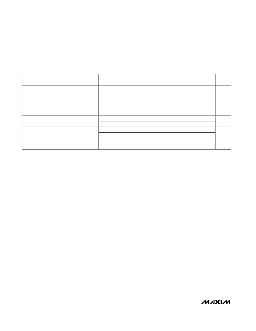
AC ELECTRICAL CHARACTERISTICS (UPCONVERTER OPERATION)
(MAX2039 Typical Application Circuit , V CC = +4.75V to +5.25V, T C = -40°C to +85°C, P LO = -3dBm to +3dBm, P IF = 0dBm, f RF =
1700MHz to 2200MHz, f LO = 1500MHz to 2000MHz, f IF = 200MHz, f RF = f LO + f IF , unless otherwise noted. Typical values are at V CC
= +5V, P IF = 0dBm, P LO = 0dBm, f RF = 1900MHz, f LO = 1700MHz, f IF = 200MHz, T C = +25°C, unless otherwise noted.) (Note 2)
PARAMETER
Input Compression Point
SYMBOL
P 1dB
(Note 4)
CONDITIONS
MIN
TYP
24.4
MAX
UNITS
dBm
Two tones:
f IF1 = 200MHz,
Input Third-Order Intercept Point
IIP3
f IF2 = 210MHz,
P IF = +5dBm/tone,
29.5
33.5
dBm
f LO = 1940MHz,
P LO = 0dBm
LO ±2IF Spur
LO ±3IF Spur
Output Noise Floor
LO - 2IF
LO + 2IF
LO - 3IF
LO + 3IF
P OUT = 0dBm
67
63
72
76
-160
dBc
dBc
dBm/
Hz
Note 1: Guaranteed by design and characterization.
Note 2: All limits include external component losses. Output measurements taken at IF port for downconverter and RF port for
upconverter from the Typical Application Circuit .
Note 3: Operation outside this range is possible, but with degraded performance of some parameters.
Note 4: Compression point characterized. It is advisable not to continuously operate the mixer RF or IF input above +15dBm.
Note 5: Measured with external LO source noise filtered such that the noise floor is -174dBm/Hz. This specification reflects the
effects of all SNR degradations in the mixer, including the LO noise as defined in Maxim Application Note 2021.
4
_______________________________________________________________________________________
发布紧急采购,3分钟左右您将得到回复。
相关PDF资料
MAX2039EVKIT
EVAL KIT FOR MAX2039
MAX2041ETP+T
IC MIXER UP/DWN HI LIN 20-TQFN
MAX2041EVKIT
EVAL KIT FOR MAX2041
MAX2042AETP+T
IC UP/DWN CONVERSION MIXR 20TQFN
MAX2042ETP+T
IC MIXER UP/DOWN CONVER 20TQFN
MAX2043ETX+
IC BASE STATION HI LIN 36-TQFN
MAX2043EVKIT
EVAL KIT FOR MAX2043
MAX2044ETP+T
IC MIXER UP/DOWN CONVER 20TQFN
相关代理商/技术参数
MAX2039ETP+T
功能描述:射频混合器 1.7GHz-2.2GHz Up/Down Mixer RoHS:否 制造商:NXP Semiconductors 频率范围: 转换损失——最大: 工作电源电压:6 V 最大工作温度:+ 85 C 最小工作温度:- 40 C 安装风格:Through Hole 封装 / 箱体:PDIP-8 封装:Tube
MAX2039ETP+TD
功能描述:射频混合器 1.7GHz-2.2GHz Up/Down Mixer RoHS:否 制造商:NXP Semiconductors 频率范围: 转换损失——最大: 工作电源电压:6 V 最大工作温度:+ 85 C 最小工作温度:- 40 C 安装风格:Through Hole 封装 / 箱体:PDIP-8 封装:Tube
MAX2039ETPD
制造商:MAXIM 制造商全称:Maxim Integrated Products 功能描述:High-Linearity, 1700MHz to 2200MHz Upconversion/ Downconversion Mixer with LO Buffer/Switch
MAX2039ETP-T
功能描述:射频混合器 1.7GHz-2.2GHz Up/Down Mixer RoHS:否 制造商:NXP Semiconductors 频率范围: 转换损失——最大: 工作电源电压:6 V 最大工作温度:+ 85 C 最小工作温度:- 40 C 安装风格:Through Hole 封装 / 箱体:PDIP-8 封装:Tube
MAX2039ETPTD
制造商:MAXIM 制造商全称:Maxim Integrated Products 功能描述:High-Linearity, 1700MHz to 2200MHz Upconversion/ Downconversion Mixer with LO Buffer/Switch
MAX2039EVKIT
功能描述:射频开发工具 RoHS:否 制造商:Taiyo Yuden 产品:Wireless Modules 类型:Wireless Audio 工具用于评估:WYSAAVDX7 频率: 工作电源电压:3.4 V to 5.5 V
MAX203CPP
功能描述:RS-232接口集成电路 5V RS-232 Tcvr w/0.1uF External Cap RoHS:否 制造商:Exar 数据速率:52 Mbps 工作电源电压:5 V 电源电流:300 mA 工作温度范围:- 40 C to + 85 C 安装风格:SMD/SMT 封装 / 箱体:LQFP-100 封装:
MAX203CPP+
制造商:Maxim Integrated Products 功能描述:Dual Transmitter/Receiver RS-232 20-Pin PDIP N Bulk
